How To Tackle Condensate Separation In Your Biogas Plant
Condensate can cause malfunctions in gas lines, fittings, measuring instruments, as well as in the gas engines and burners. Targeted condensate separation is, therefore, essential for gas systems.
But let’s start at the beginning.
How does water get into the biogas?
Biogas is produced in a digester. The biomass, also called substrate, does not only consist of organic material. The biogas is created from organic material. The largest component of the substrates is usually water. The fermentation substrate in the digester, therefore, consists of 85 – 95 % water.
The biogas produced in the digester collects above the liquid level in the digester. The fermentation substrate is heated to accelerate the formation of biogas. In the mesophilic mode, the temperature is between 32 – 40 °C, while in the so-called thermophilic mode, the temperature is between approximately 50 – 65 °C.
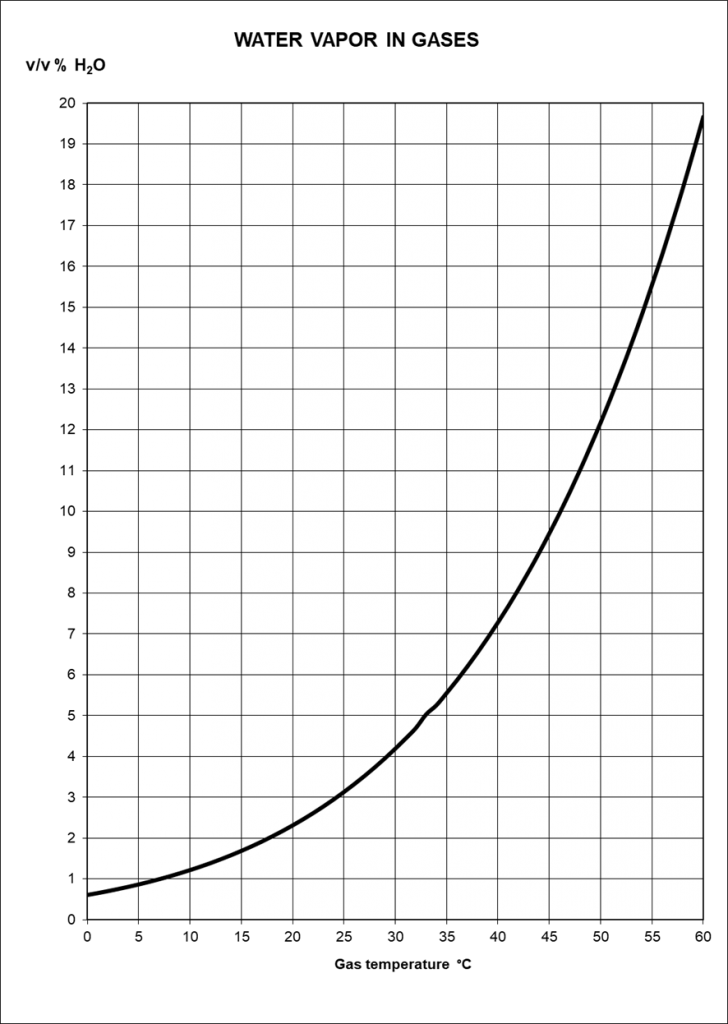
Biogas, like all gases and air, absorbs water as vapour. In addition to the actual gas components, a gas always contains moisture in the form of water vapour. However, the proportion of water vapour is not constant. Gases have the ability to absorb more water with increasing temperature.
Absolute Humidity
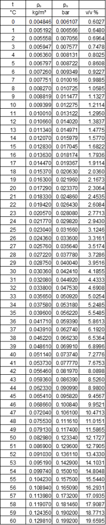
Water vapour can be absorbed in gas until it is saturated. Saturation is the point at which the water vapour can no longer be absorbed into the gas. If more water vapour is added or the temperature decreases, the water vapour condenses and liquid water is formed. Absolute humidity is the water vapour concentration at which only water vapour is present. The information is given as concentration (g/m³), volume per cent (v/v%) or also as partial pressure (mbar, Pa).
Relative Humidity
The gas in the digester is usually completely saturated with water vapour. However, gas does not always have to be 100% saturated. The air almost always contains less water vapour, and the relative humidity is below the maximum possible saturation. The relative humidity is expressed as a percentage of the maximum humidity at the given temperature. The relative humidity of the air should be approximately between 40 – 70 % to allow comfortable breathing.
Why is water (condensate) harmful in biogas?
The temperature in the digester is usually significantly higher than the ambient temperature. The biogas leaves the digester at e.g. 40 °C and is completely saturated with water vapour.
At a temperature of 40 °C, there is thus 51.1 g of water vapour in one cubic meter of gas. The gas is discharged via a pipeline to the gas consumer. The ambient temperature is 25 °C and the gas cools along the way so that at the end of the pipe the temperature is 30 °C.
The gas is cooled by the water vapour. The cooling of the gas reduces the gas’s ability to absorb water vapour. The water vapour condenses to water and is then in liquid form in the gas line. At 30 °C, the gas can only absorb 30.4 g of water vapour per cubic meter. Thus, cooling of only ten degrees produces more than 20 g of water per cubic meter of gas.
The gas is still 100% saturated with water vapor!
However, the absolute humidity is significantly lower.
If the water vapour condenses, the water is then in the gas line. The water naturally collects at the lowest point in the pipeline system. However, the lowest point can also be a water pocket in a pipeline, which has been created by a faulty installation. The water can cause a blockage, and the gas cannot continue to flow.

When laying pipes, especially plastic pipes in the ground, care must therefore be taken to ensure that they are laid carefully. The line must not “sag”.
- This would cause a low point to form in the pipe. Condensate collects there and cannot drain off.
- A high pressure loss occurs.
- Pulsations occur in the line.
However, water in the piping system has other disadvantages:
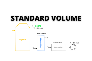
- The water vapor takes up a lot of volume. This increases the gas volume. However, the water vapor is ballast and does not contribute to the energy conversion. If the gas in our example has a temperature of 0 °C, the water vapor has a volume fraction of more than 7.2 %. At 30 °C, the volume fraction is already reduced to 4.2 %.
- Cooling the gas and removing the water leads to a lower volume of the gas without reducing the energy content. The pressure losses in the pipe power system are reduced and, of course, also the energy required for the necessary pressure increase with a blower.
- The condensate is not pure water. Various other substances are transferred from the digestate into the gas. Organic acids and dissolved salts, for example, can be transferred into the gas phase. These substances can adhere to fittings and other installations and lead to corrosion and further malfunctions, e.g. due to the formation of deposits.
How can the condensate be removed from the biogas?
The condensate can cause malfunctions in gas lines, fittings, measuring instruments, as well as in the gas engines and burners. Targeted condensate removal from the gas system is therefore always necessary.
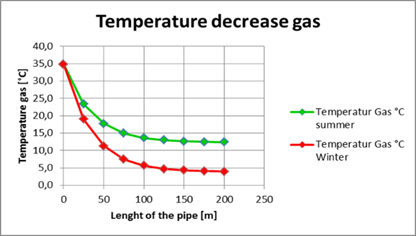
The amount of condensate that must be removed depends on the temperature difference between the temperature of the gas as it exits the digester and the ambient temperature. Of course, the amount also depends on the volume flow.
The ambient temperature can vary over the course of a day. It is cooler at night than at noon, so more condensate is produced at night. The same is true over the seasons. If temperatures are significantly lower in winter than in summer, more condensate is produced than in summer.
If the gas is only cooled to the natural ambient temperature, the moisture content of the gas depends on the temperature. The gas quality is therefore not constant. If the gas cools down further on its way, condensate can also form at a later point in time.
Controlled Condensation
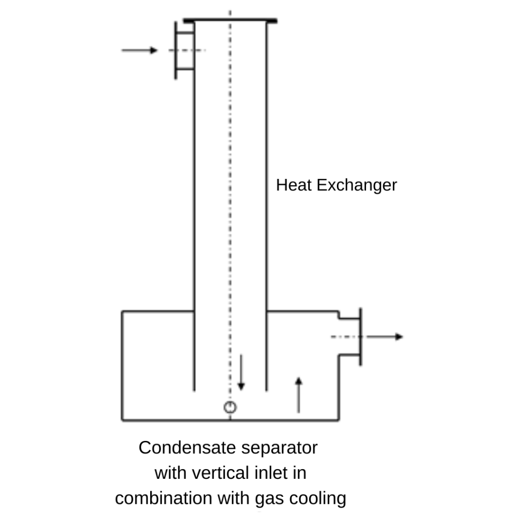
In addition to the uncontrolled condensation of the water vapour, condensation can also be brought about in a controlled manner. The biogas is directed through a heat exchanger and cooled down to a defined temperature. The gas can thus have a constant quality with a low water vapour content. The temperature during targeted cooling must usually be above the freezing point to prevent malfunctions. For most applications, however, this prevents subsequent condensation of the water vapour.
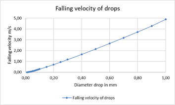
The water vapour condenses into small droplets as it cools. In a gas pipeline, the gas flows at a speed of several meters per second. If the pressure loss is to be low, a velocity of 2 – 4 m/s is recommended. At this speed, however, droplets are entrained. The drops cannot settle, they are carried along by the flow and can thus lead directly to malfunctions, e.g. at the gas engine. It is therefore necessary to specifically reduce the velocity in an apparatus to allow sedimentation. The velocity of the gas depends on the droplet size. With a smaller droplet diameter, the gas velocity must be lower.
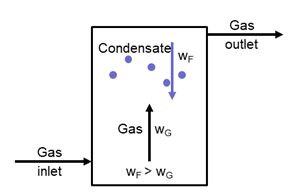
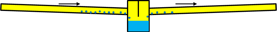
A condensate separator, therefore, consists of a tank that has a significantly larger diameter than the pipeline. The diameter of the condensate separator is therefore also dependent on the volume flow.
Condensate Separation
The condensate separator must always be located at the low point of the piping system. The water can then flow into the tank by gravity. The collected condensate is discharged from the tank manually or automatically.
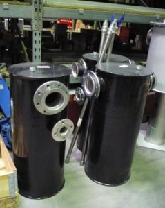
The condensate separation collection tanks are of simple design. The tanks can be adapted to the installation situation.


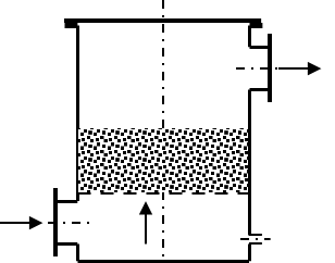
A good variant is the “gravel filter”. This condensate separator contains a filling with coarse gravel or a comparable packing. The gravel increases the surface area and also retains coarse dirt. The gravel filter is therefore preferably installed directly after the digester. In the past, gravel filters were also used as flame arresters; today, the gravel filter no longer fulfils this application.
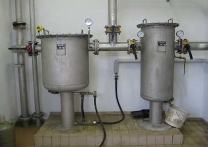
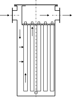
A fine filter can also be used to separate the condensate from the gas. The container contains filter cartridges made of ceramic material or plastic. The filter cartridges can additionally retain solid dirt particles. A good cleaning quality can be achieved with a fine filter.
Installation of Condensate Separation Systems
The condensate traps can be installed both above and below ground. However, the condensate separation must always be located at the lowest point of the piping system. If there is a risk of outside temperatures below 0 °C, the condensate separator must be protected against freezing of the water.
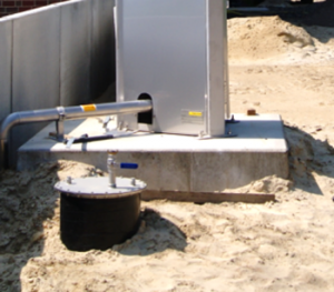
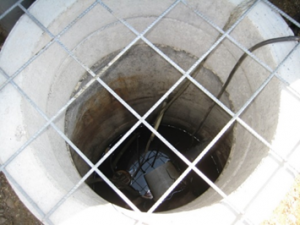
In the case of installation on the ground, special attention must be paid to work safety. Condensate separation can always be associated with the escape of small amounts of biogas. If the condensate separator is installed in a shaft, there is a risk that the gas cannot escape. Thus, there is not only the risk of a possible explosion but also the risk of poisoning or suffocation during maintenance work.
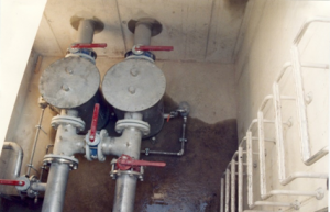
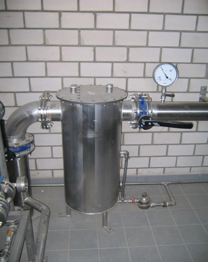
Condensate separation in a shaft in front of a gas storage tank.
Condensate Drainage
The collected condensate must be discharged from the collection tank. In the simplest case, the condensate can be discharged manually via a valve, e.g. a ball valve. Other options include discharge via a siphon and with a mechanically acting ball float valve.
The discharge of the condensate is also associated with the escape of small quantities of gas. This can create a dangerous explosive atmosphere. Therefore, the immediate discharge area of one meter is zone 1 in the sense of ATEX. Especially when using a siphon, uncontrolled gas leakage must be expected. Sealing is achieved by means of a water column, the height of which depends on the gas pressure. If a pressure surge occurs due to a malfunction, the sealing liquid can be discharged. The trap can no longer retain the gas, so the gas escapes in an uncontrolled manner.
The best material for a mechanical steam trap is stainless steel. Steam traps made of aluminium alloys are not resistant in all cases and will corrode.
Technical cooling – gas drying plants
Condensate separation can also be achieved in a targeted manner if the biogas is cooled down to the desired temperature using suitable measures. For this purpose, the gas is passed through a heat exchanger. With a cooling medium, e.g. cold water, the gas can be brought to a lower temperature level.
Cooling the gas requires energy. The energy requirement is made up of two components. One factor is the actual cooling of the gas. The second factor is the energy required for the condensation of the water vapour to liquid water. The larger component is the energy required for the condensation of the water vapour.
The provision of cold for indirect cooling can be done in different ways:
- Cold water
- Refrigerant
Chilled Water
Most gas cooling systems on the market use chilled water.
The cold water is generated in a chiller. This is a chiller that transfers the cold to water via the refrigerant in an internal heat exchanger. The cold water is passed through the gas/water heat exchanger. The water heats up while the gas cools down, and the heated water is cooled down again.
However, it is also possible for the refrigeration machine to inject the compressed refrigerant directly into the heat exchanger, which cools the gas. Energetically, this process is more advantageous. Technically, it is somewhat more complicated to set up the process correctly.
Gas cooling systems with a chiller are easier to install and operate. The water can also be mixed with glycol, if necessary so that lower temperatures of 3 – 4 °C can be achieved without the liquid freezing.
Direct Cooling
Another possibility is to cool the gas directly.
In this case, the gas is brought directly into contact with the cold water. A heat exchanger is not required. The gas is sprayed by the water so that the gas very quickly assumes the water temperature. The gas moisture also condenses in the process.
This method is useful when the gas is dirty, e.g. due to excessive foaming in the digester. The water can only be circulated to a limited extent and exchanged according to the degree of contamination.
The Heat Exchanger
Important for gas cooling is the heat exchanger. Since the biogas usually has only low operating pressure, the pressure loss must be kept as low as possible. However, low-pressure drops result in a higher exchange area.
Most heat exchangers are classical shell-and-tube heat exchangers. The gas flows in the inner tubes, and the cooling water flows around the tubes. These heat exchangers are robust, the pressure loss can be kept low with good planning.
An alternative is the finned heat exchanger. The tubes through which the cold-water flows have fins on the outside. The fins result in a large surface area so that the pressure drop can be kept very low.
Condensate Separation Drain
The condensate produced during cooling must be drained from the heat exchanger with a condensate separation drain. If the heat exchanger is installed horizontally, a gradient in the direction of the condensate drain must be considered. Shell-and-tube heat exchangers can also be installed vertically. The condensate can be collected in a collecting tank and drained off.
After cooling, the gas is still 100% saturated with water vapour. However, the absolute moisture content is significantly lower. For some requirements, e.g. if the gas is to be further treated in an activated carbon filter, lower relative humidity can be advantageous. For this purpose, however, the gas must be heated again. The temperature of the gas must be several degrees above the outlet temperature of the heat exchanger. Heating can be achieved in various ways.
Heating …
- … in a further heat exchanger with a heating medium.
- … with a gas compressor.
- … via a recuperative heat exchanger.
Heating with another heat exchanger operated with warm water can heat the gas to the desired temperature. The warm water can be taken, for example, from the cooling water circuit of the gas engine. Alternatively, in gas cooling systems that inject the refrigerant directly, the condensation heat that is otherwise released to the ambient air via the absorber can also be used.
Often, a gas compressor is still required, which must compress the gas to the required operating pressure. If it is possible to install the gas compressor downstream of the gas heat exchanger, the compression will heat the already cold gas to a higher level. If the pressure difference is sufficiently large, required gas heating is already achieved without further installation and energy input.
Recuperative Heat Exchangers
The third possibility is to use a recuperative heat exchanger. If the warm gas, which is to be cooled, is first passed through a heat exchanger on the other side of which the cold gas flows. The cold gas cools the warm gas and heats the cold gas. This mode of operation has the advantage that the gas can be easily reheated. At the same time, pre-cooling of the warm gas takes place. The warm gas is cooled to the desired temperature in a further heat exchanger in the usual way. The effort for cooling can thus be reduced and the operating costs can be lowered.
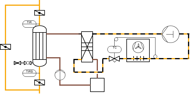
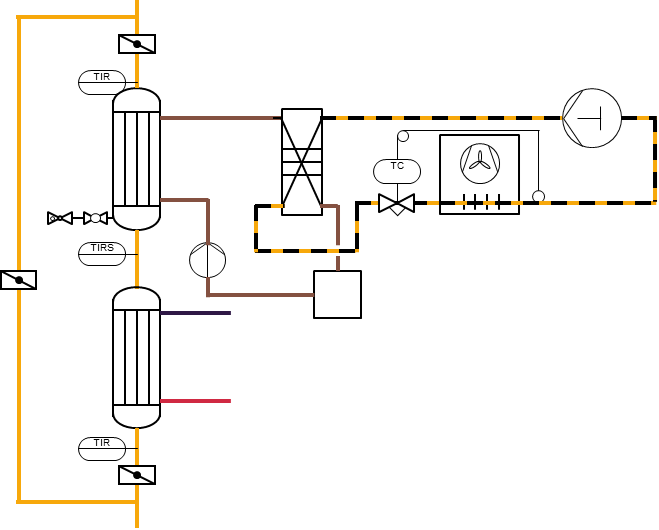
Gas cooling with tube bundle heat exchanger and chiller with plate heat exchanger
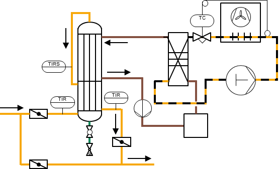
Gas cooling with tube bundle heat exchangers for cooling and reheating chiller with plate heat exchanger
Gas dehumidification with recuperative heat exchanger for cooling and reheating, chiller with plate heat exchanger
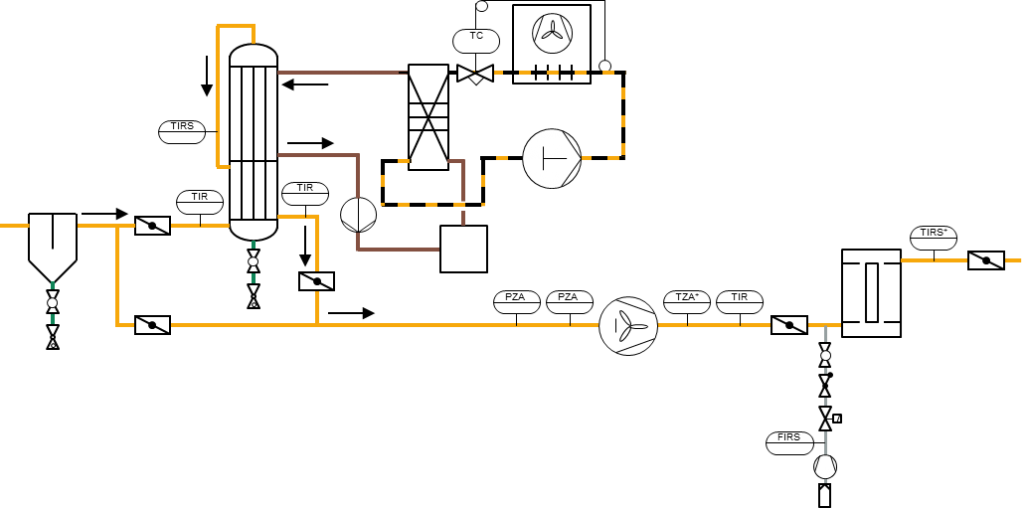
Condensate separation by water pot, gas cooling with a recuperative heat exchanger with reheating of the gas, reheating with a centrifugal compressor for the operation of an activated carbon filter

1 Comment
Anonymous · January 1, 2023 at 9:00 am
I need to to thank you for this good read!! I certainly loved every bit of it. I have you bookmarked to check out new stuff you postÖ