Gas flares for biogas
Biogas is the fuel for gas engines, fuel for boiler plants as well as raw material for the production of bio natural gas. But even the best plants for utilising biogas can occasionally experience malfunctions. However, the production of biogas cannot simply be stopped. All plants, therefore, require gas flares.
As soon as the gas holder of the biogas plant is completely filled, the biogas must be disposed of without causing any damage. The discharge of unburned methane into the atmosphere is also harmful for several reasons:
- The biogas leads to unpleasant odour emissions
- Methane from the biogas mixes with oxygen from the air. Combustible mixtures are formed. Contact with an ignition source (sparks, hot surfaces) can lead to fires and explosions.
- Methane is a greenhouse gas that is harmful to the climate. It is about 25 times more harmful to the climate than carbon dioxide
A gas flare is therefore an important component in a biogas plant. The flare must be functional if an unforeseen disturbance or interruption of the usual gas utilisation occurs.
The gas flare burns the methane to carbon dioxide and water. The resulting heat, like the combustion products, is released into the atmosphere.
CH4 + 2 O2 → CO2 + 2 H2O + energy
The CO2 as a combustion product is significantly less harmful. Organic biomass produces biogas, therefore it also remains in the biological cycle. No additional carbon dioxide is added to the atmosphere, as is the case with the combustion of fossil fuels.
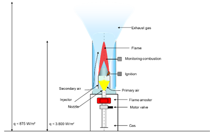
A gas flare is, simply put, an oversized Bunsen burner. Basically, a flare works according to the same principle.

The essential components of a gas flare are
- Burner with
- Nozzle
- Injector
- Combustion chamber/windshield
- Ignition
- Flame monitoring
- Safety fittings
- Quick-closing valve – closing time < 1 second
- Flame arrester
- Control for automatic operation
- Initiation of the ignition process
- Monitoring of combustion
- Control of the shutdown process
- Shutdown in the event of malfunctions
- Manual operation
Functions of gas flares
A flare is a safety device. In the event of a malfunction in the utilisation process, e.g. if the gas engine fails unexpectedly, the gas production cannot be switched off immediately. Gas production is a biological process. The bacteria utilise the available substrate and convert it into biogas. We can store biogas only to a limited extent. However, as soon as the gas storage is filled, the gas must be safely disposed of.
A flare should only operate when a malfunction is present. In this situation, we must ensure that the burning process can be started even in adverse conditions, e.g. wind and rain. For the period of the malfunction, the gas must be burnt. In the case of longer operational disturbances, we must interrupt the substrate feed, also in order to save substrate.
However, this is not possible in production processes that generate wastewater and waste. In these cases, too, the gas flare must be able to burn the gas safely.
A large number of biogas plants work with membrane roofs. These systems cannot provide sufficient gas pressure. The necessary gas pressure must be provided with the help of a gas compressor. In this case, we recommend providing a separate compressor. This avoids conflicts with other gas consumers. Since the combustion of the biogas must also function in the event of a failure of the general power supply, the integration into the emergency power supply is easier to realise.
Gas Flares For Gas Storage Tanks
The filling level of the gas storage tank switches on the gas flare. For this purpose, we must measure the filling level of the gas holder. If the fill level reaches a predefined maximum value, e.g., 95%, the flare starts operating. The electric ignition or pilot burner starts and then the gas valve opens.
The gas mixes in the injector with the necessary air burns in the flame tube. A UV probe or an ionisation sensor shall monitor the combustion process. The ignition restarts, in case of short interruptions. If there is a longer interruption, the gas supply must switch off and issues a fault message.
If the gas storage tank level drops to a level of 85 %, for example, the flare switches off. This prevents unnecessary gas losses. When the fill level reaches the maximum value again, the burning process starts again. We can operate digesters with fixed roofs or biogas plants equipped with low-pressure gas storage tanks without a gas compressor. The inlet pressure is sufficient to operate the flare. In this case, the starting process can also be carried out via pressure.
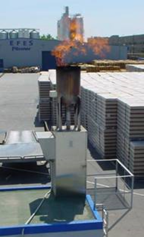
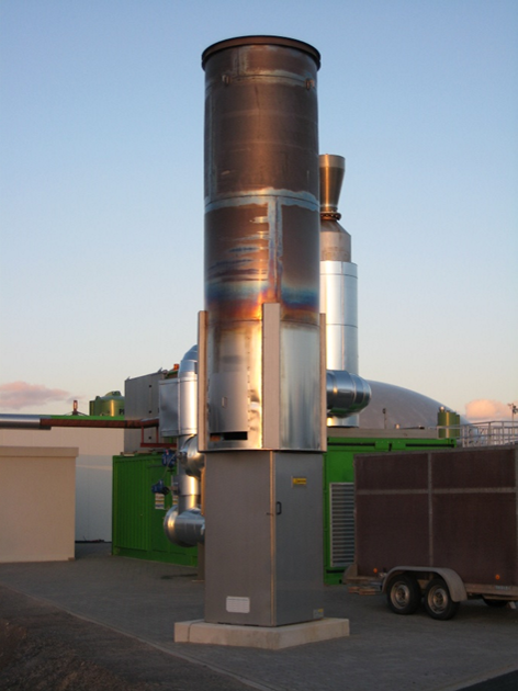
Open and concealed burning gas flares
Depending on the visual requirements, we can design the gas flares with an open burning flame or also with a concealed burning flame.
Concealed gas flares are used when the visible flame causes a nuisance to the surroundings. With these flares, the combustion quality is optimised and the flame length is reduced. The flame is enclosed by a flame tube of sufficient length.
Open flares are simpler and can be used if the flame does not disturb neighbours or traffic. Technically, these flares are somewhat simpler.
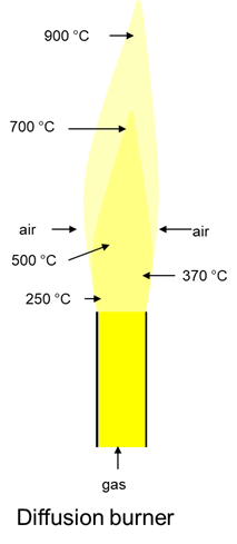
Flame types
Depending on the combustion conditions, the flame can take different forms. For the operator of a flare, it is often of greater importance to have an invisible or barely visible flame. This helps to avoid irritation with the neighbourhood. The production of colourless flames depends on a good mixing of the fuel gas with the air and the shortening of the flame length.
A simple flare, as is also frequently used, consists of a pipe from which the biogas flows. Only when the gas outside the pipe comes into contact with air can a combustible gas-air mixture form. However, the mixing is more incomplete than complete.
There is not always enough oxygen in the mixture to ensure complete combustion of the methane to the carbon dioxide. The oxygen can only enter the gas by diffusion, which is why the burner is also called a “diffusion burner”. The combustion is incomplete, the flame burns yellow and can also tend to form soot.
The flame temperature is low.
A diffusion flame is not suitable for good combustion of the biogas.
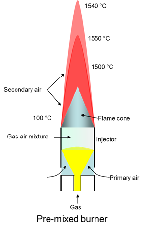
Premixed burner
In a premixed burner, the gas flows from a nozzle into the injector and draws in the air (primary air).
The gas and air are premixed in the injector. The premixed gas-air mixture is ignited and burns with a short, colourless flame. The combustion temperature is higher and combustion is (almost) complete.
With suitable devices, the addition of secondary air can be controlled. This can also influence the flame temperature.
The flame length depends on the volume flow. The gas is divided among several burners for larger volume flows to prevent the flames from becoming too long.
Temperatures
During the combustion of methane (CH4), temperatures of up to 1900 °C can occur in the flame. Lower temperatures are present on average in the combustion chamber. The following points influence the temperatures in parts of the flame and in the burnt exhaust gas:
→ Heat emission (radiation) to the environment
→ Excess air during combustion
The exhaust gas volume increases through the supply of excessively stoichiometric amounts of air. The entire volume heats up and the exhaust gas temperature decreases
Influencing the combustion temperature
Diffusion burner
→ No possibility
Premixed burner
→ Control of the combustion air by air volume regulation.
→ For higher required combustion temperatures, we can equip the combustion chamber with thermal insulation.
Modern biogas flares are designed as premixed burners (injector burners). This ensures a combustion temperature of > 850 °C. That way, we can achieve a colourless flame with good burnout behaviour.
Safety distances
The energy released during the combustion of the biogas in the flare makes itself felt as heat radiation. For a flare that burns 1,000 m³/h, for example, this is 5,000 – 7,000 kW. When you are near the flare you can feel some of the heat directly through the radiation. The exhaust gas also dissipates a substantial part of the heat. The high temperatures can of course lead to hazards for the surroundings and for the people working there.

It is therefore necessary to place the flare at a safe distance from other buildings and installations. We must consider escaping hot exhaust gases to prevent damage to people and materials.
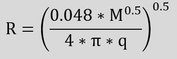
We can estimate the intensity of the radiation and the resulting distances with the following relationship.
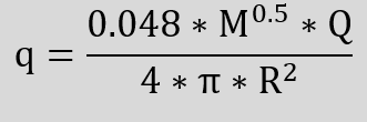
q Heat flux density
M Molar mass of the gas
Q Maximum heat output
R Distance from flame centre
m Mass of the gas
Hi Lower heating value
Q m * Hi
ε Emissivity ratio = 0.048 * M0.5
W/m²
Da
W
m
kg
W/kg
W
–
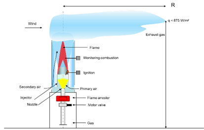
Influence of the distances on the radiation intensity
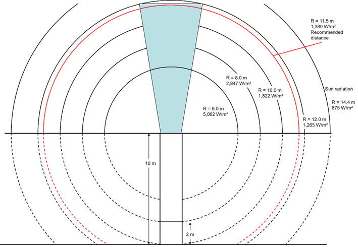
Illustration of the necessary distances to reduce the radiation effect.
Visible flame, concealed flame
We often distinguish gas flares by whether the flame is visible or not. If we expect no disturbance to the neighbourhood from the occasional appearance of a flame, we can construct the flare more simply.
If there are higher demands, we must design the flame so that it burns in a combustion chamber and is practically invisible. Only some weather conditions, e.g. strong winds, can cause flames to become visible for a short time.
For this purpose, the design of the burner keeps the flame short and optimises the air supply.
A concealed flame also ensures that the combustion temperature is at least 850 °C. This allows for the greatest possible elimination of the flame. This makes it possible to achieve the greatest possible burnout. However, the combustion temperature is not so high that a significant nitrogen oxide concentration does not occur.
For biogas and sewage gas, these flares are perfectly adequate as they contain practically no other pollutants (apart from H2S).
If landfill gas, which has a similar composition, is to be burnt in a flare, the requirements are greater. Landfill gas can contain chlorine-containing substances in particular. During combustion, other hazardous substances such as dioxin can also be formed from these compounds.
To avoid the formation of harmful substances, combustion must take place at a temperature of at least 1,000 °C and a residence time at this temperature of at least 0.3 seconds. For this purpose, the combustion chamber shall be sufficiently large and equipped with thermal insulation.

0 Comments