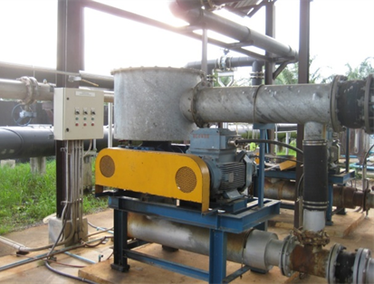
Gas blowers: Increasing the gas pressure in biogas plants
To transport the biogas from the digester to the gas consumers, such as the gas engine or the gas burner of a boiler plant, the gas must have a higher pressure. As the gas flows through the pipelines, cleaning equipment and metering devices, a pressure loss occurs. The pressure loss is the energy required to overcome the friction losses at the pipe wall and other resistances.
The higher the flow velocity of the gas, the greater the energy expenditure and pressure loss.
The gas consumer, i.e. a gas engine, the gas burner and also the gas flare, need a pre-pressure to be able to fulfil their function.
Gas Pressure
The pressure that can occur in a biogas plant depends on the construction of the biogas plant and especially on the digester. The upper part of the digester collects the biogas. The volume of the gas collection space is practically constant. Pressure builds up when there is more gas in the space than corresponds to atmospheric conditions.
Compression of the gas then takes place. As a result of the gas compression, the pressure increases. The degree of gas compression and the level of gas pressure depends on the construction of the digester. The gas pressure must be able to be absorbed by the structure, in this case, the digester. If the digester has a sufficiently stable roof, for example, made of concrete or steel, overpressures of up to 50 mbar may be possible.
If the digester has a membrane roof, the operating overpressure is significantly lower. With single-skin roofs, the overpressure is very low at around 1 – 3 mbar. With double-shell roofs, which are stabilised with compressed air, the pressure is 5 – 10 mbar, depending on the size and design.
In the case of digesters with fixed roofs, with clever planning, it is possible to operate the gas consumers without an additional increase in pressure. This means that the biogas plant has one component less. This eliminates maintenance, repairs and energy consumption.
Gas fans and blowers
However, most digesters have membrane roofs. Lagoon systems are not possible without membranes. An increase in gas pressure will therefore always be necessary.
We use gas compressors to generate the necessary pressure. The gas compressors use mechanical energy to compress the compressible medium gas with suitable measures. For most applications, a gas overpressure between 100 – 200 mbar is required, only occasionally a higher pressure. If the biogas is to be upgraded to bio-natural gas, significantly higher pressure is required. We do not consider these applications further here.
Three different designs are available for increasing the pressure in biogas plants:
- Centrifugal fans
- Side channel blowers
- Rotary piston blowers (Roots blowers)
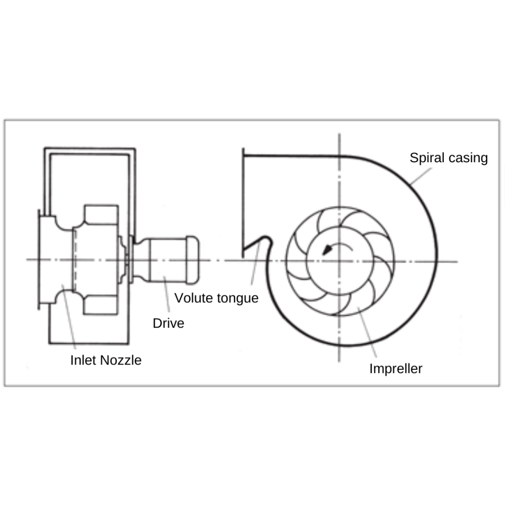
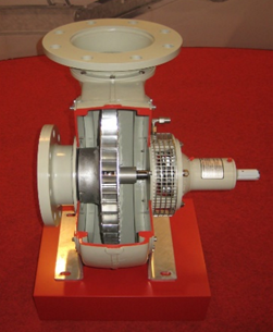
Centrifugal fans
With the centrifugal fan, the gas enters the spiral housing horizontally. The impeller is located in the scroll housing. The rotating impeller converts the mechanical energy into pressure and speed energy. The tongue is the narrowest area between the casing and the impeller. A backflow of gas is possible there. Due to the possibility of gas backflow, the unneeded gas volume recirculates. Additional volume control is not necessary.

Advantages
- Good for large volume flows
- No additional volume controls are necessary
- Low energy consumption
Disadvantages
- No high pressures > 200 mbar suitable possible
Side-channel blower
The side channel blower compresses gas by dynamic energy input. The gas enters on the suction side (A, 6). The impeller (4) compresses the gas and exits on the discharge side (B, 7). Between the inlet and the outlet is the interrupter (8). The interrupter prevents the gas from flowing back.
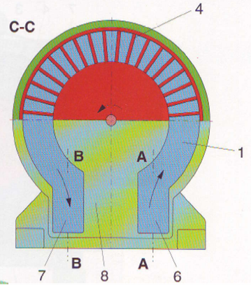
In contrast to centrifugal fans, the gas cannot flow back inside the housing of side channel blowers. If the gas intake fluctuates, we must control the volume flow must in a different way. However, if the volume flow changes, the pressure should remain constant! We can achieve volume flow control with a side-channel compressor by means of an overflow valve.
If less gas is taken off by the consumer, the gas pressure on the outlet side of the gas compressor increases. The overflow valve is installed on the discharge side in the bypass. If the pressure rises, the mechanically operating valve opens. The gas flows back to the suction side of the compressor. In this way, the pressure is kept constant. The excess gas is circulated. However, care must be taken that the gas does not become too hot due to the compression.
Advantages
- Well suited for small volume flows
- Pressures up to 400 mbar possible
Disadvantages
- Volume control only possible with a circulation controller
- Poor efficiency
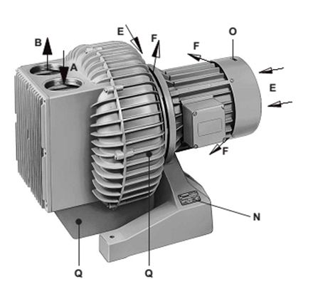
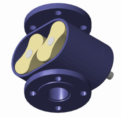
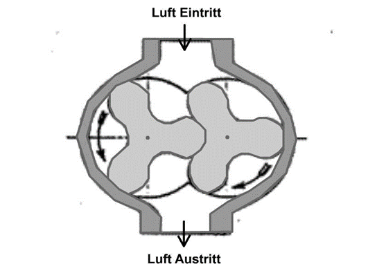
Rotary piston blowers (Roots blowers)
The rotary piston blower works similar to the side channel blower but as a displacer. Compression takes place without internal compression. Two- or three-bladed rotors rotate in the housing and compress the gas. There is no internal backflow of the gas. Rotary blowers can handle large volume flows with differential pressures of up to about 1 bar.
Advantages
- Well suited for large volume flows
- Pressures up to 1 bar possible
Disadvantages
- Volume control only possible with a circulation controller
- Poor efficiency
Notes on planning and operation
Volume flow and pressure
When planning the gas system, i.e. the pipelines with fittings, gas purification systems, condensate separators and measuring devices, care must be taken to keep the pressure loss as low as possible. It may be more economical to choose a nominal diameter larger and to reduce the expenditure for pressure generation.
In the case of gas consumers, we should ask ourselves what pressure do we actually need? The manufacturers’ specifications sometimes contain very high safety margins.
In a gas engine, the pressure is greatly reduced before it enters the engine. The pressure loss at the engine mainly occurs at the gas control line. Optimising the Nominal diameter can lead to significant energy savings over a longer period of time.
If the manufacturer’s characteristic curve refers to air, these values must be corrected to the density of the biogas present. In an unfavourable case, the blower’s output may otherwise be too low
Materials
When selecting the materials, care must be taken to ensure adequate corrosion protection. Stainless steels are usually suitable, as are common light metal alloys. Manufacturers also offer special coatings.
During operation, the risk of corrosion is low. Due to the heat generated during compression, it is dry inside the compressor. However, during a standstill, condensate can accumulate in the compressor.
The condensate can interfere with the start of the compressor and also lead to corrosion. Experts recommend installing the compressor at a high point. The piping must be laid in such a way that no condensate can flow into the fan.
Explosion protection
Not only the electrical components must meet the requirements of explosion protection. The drive motor must have at least “increased safety”.
Measuring devices in the immediate vicinity must also be installed with explosion protection, e.g. intrinsically safe. However, engineers must also design the mechanical components so that no ignition spark or excessive surface temperature can lead to an explosion.
Ignition sparks can be avoided by using suitable materials, e.g. stainless-steel impeller and stainless-steel housing. The penetration of foreign bodies, such as screws, must not cause sparks. We must prevent the hot running of shafts by design.
Safety devices
Protection against impermissible negative pressure is necessary. To prevent the ingress of air and the associated risk of the formation of an explosive atmosphere, the redundant arrangement of negative pressure switches may also be necessary. In this way, the blower can be safely switched off in the event of critical negative pressure.
It also makes sense to protect the blower against high temperature during a partial load operation. A temperature switch interrupts operation if a hazard is to be expected. Pressure monitoring is advantageous and can also be used for shutdown in the event of further requirements.
Why does it not make sense to operate gas compressors with speed control?
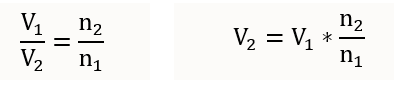
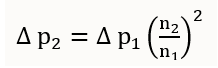
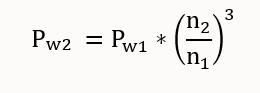
Gas compressors are often operated with a frequency converter to control the volume flow. By changing the speed, the volume flow also changes. However, this mode of operation does not consider that the pressure also changes. While the volume flow changes linearly with the speed, the change in pressure is squared. The power requirement of the fan even changes to the third power.
The laws of proportionality, therefore, apply to gas compressors.
A change in the delivery rate of a blower due to a change in the speed of the blower, therefore, leads to different, proportionally behaving properties.
- The volume flow of a fan changes proportionally to the rotational speed
- The total pressure changes with the square of the rotational speed
- The power requirement changes with the speed at the shaft with the third power
- V1 = Volume flow gas State 1 m³/h
- V2 = Volume flow gas State 2 m³/h
- ∆p1 = Pressure difference State 1 mbar
- ∆p2 = Pressure difference State 2 mbar
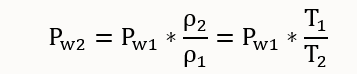
- Pw1 = Power demand state 1 kW
- Pw2 = Power demand state 2 kW
- T1 = Temperature State 1 K
- T2 = Temperature State 2 K
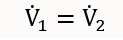
- The volume flow of a blower remains constant even if the temperature of the gas changes.
- The mass flow, on the other hand, changes.
- The density also changes with the temperature.
- This also changes all functions that depend on the temperature.
Calculation example
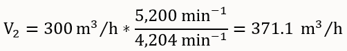
A centrifugal blower delivers a volume flow of 300 m³/h at a speed of 4,204 min-1. The pressure is 110 mbar, and the power requirement is 10 kW.
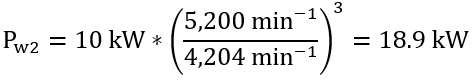
The speed is to be increased to 5,200 min-1.
- What is the subsequent volume flow rate?
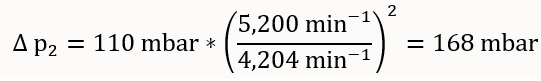
- How high is the pressure after increasing the speed?
- How high is the power requirement?
Volume flow
Pressure
Power requirement
Other useful parameters
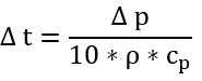
Temperature increase
When a gas is compressed in a gas blower, part of the mechanical energy is converted into heat.
- The gas, therefore, has a higher temperature after compression.
Example
pE = Inlet blower pressure
pA = Outlet blower pressure
∆p = Pressure difference
ρ = Density of the gas
cp = Specific heat of the gas
∆t = Temperature increase
0 mbar
120 mbar
120 mbar
1.284 kg/m³
1.251 kJ/kg*grd
7.5 grd
Conversion of the volumetric flow from the characteristic curve to a gas of a different density
The characteristic curves of gas compressors but also of pressure-reducing valves are usually related to air. The conversion to gases with other densities is done with the relation:
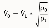
V0 = Volume flow from the characteristic curve m³/h
V1 = Volume flow of the gas m³/h
ρ0 = Density of the gas from the characteristic curve kg/m³
ρ1 = Density of the gas kg/m³
Example
A gas with a density of 1.221 kg/m³ is to be compressed to 150 mbar. The volume flow is 200 m³/h. The characteristic curve of the blower is given with air with a density of 1.293 kg/m³.
How high must the volume flow for the gas be at the same pressure?
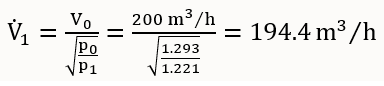
The blower is sufficiently dimensioned as the same pressure can already be achieved with 194.4 m³/h, referred to air.

2 Comments
Giuseppe · September 13, 2022 at 2:44 am
Good explanation. Would be great if you can share some reference like book or standards. Thank you Giuseppe
Celsigas · September 13, 2022 at 6:44 am
Hi Giuseppe, thanks for your feedback! Much appreciated. I’ll add our references to the next update of this post. -Danny @Celsigas